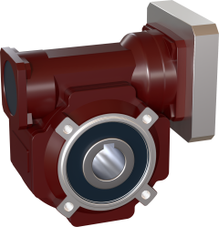
SVS-050 Right Angle Gearbox
SVS-050 Right Angle Gearboxes can output up to 94 Nm (depends on ratio), and are suitable for servomotors up to 500W.
Calculate your machine and find the required gearbox output torque using this tool

SVS-050 Right Angle Gearbox
SVS-050 Right Angle Gearboxes can output up to 94 Nm (depends on ratio), and are suitable for servomotors up to 500W.
Calculate your machine and find the required gearbox output torque using this tool