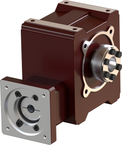
MQ-050 Right Angle Gearbox
MQ-050 Right Angle Gearboxes can output up to 215 Nm (depends on ratio)
Calculate your machine and find the required gearbox output torque using this tool

MQ-050 Right Angle Gearbox
MQ-050 Right Angle Gearboxes can output up to 215 Nm (depends on ratio)
Calculate your machine and find the required gearbox output torque using this tool