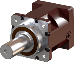
SGH-0400 Planetary Gearbox SGH-0400 gearboxes can output up to 550 Nm (depends on ratio) Calculate your machine and find the required gearbox output torque using this tool Engineering Calculator Horizontal TabsOverview Performance data Number of stages: 1, 2 and 3 stages Transmission ratios: 3:1 to 300:1 Backlash: ca. 0, <1’, <3’, <5’, <10’ Efficiency Up to 97% Input motor flanges: For all servomotors Output shaft Smooth Output Shaft Output Shaft with Key Splined Output Shaft Typical Applications Gantries Linear Tracks for Robots Packaging Robotics Linear Actuators General Automation Advantages Highly accurate positioning High torsional rigidity Highly reliable thanks to heat treated gears Very high radial load tapered roller bearings Very compact design Very high torque density Easy motor installation Specifications S5 Duty Cycle Technical Data Stages Ratio T2N (Nm) T2max (Nm) T2E(1) (Nm) N1n (min-1) N1max (min-1) F2Rmax (N) F2Amax (N) C (Nm/arcmin) η % M (kg) Δφ (arcmin) 1 3 410 550 1230 2000 3000 8000 11000 37 97 8 ca. 0 <1’ <3’ <5’ <10’ 2 9 410 550 1230 2000 3000 8000 11000 35 94 10 ca. 0 <1’ <3’ <5’ <10’ 12 410 550 1230 2000 4000 8000 11000 35 94 10 15 410 550 1230 2000 4000 8000 11000 35 94 10 21 410 550 1230 2000 3000 8000 11000 35 94 10 30 410 550 1230 2000 4000 8000 11000 35 94 10 3 36 410 550 1230 2000 4000 8000 11000 33 91 12 ca. 0 <1’ <3’ <5’ <10’ 45 410 550 1230 2000 4000 8000 11000 33 91 12 60 410 550 1230 2000 4000 8000 11000 42 91 12 75 410 550 1230 2000 4000 8000 11000 42 91 12 90 410 550 1230 2000 4000 8000 11000 33 91 12 105 410 550 1230 2000 4000 8000 11000 42 91 12 120 410 550 1230 2000 4000 8000 11000 40 91 12 150 410 550 1230 2000 4000 8000 11000 42 91 12 210 410 550 1230 2000 4000 8000 11000 43 91 12 300 410 550 1230 2000 4000 8000 11000 40 91 12 (1) T2E Up to 1000 times during the gearbox's lifetime Subject to technical improvements without prior notice General Data Housing Surface Temperature °C -10°C to +90°C Ingress Protection IP65 Sound Levels dB(A) ≤71 Design Life Hours 20000 Lubrication Synthetic Oil Lubrication Turning Direction Same as Input Moment of Inertia Stages Ratio J (kg·cm2) per Motor Shaft Diameter ⌀≤14 ⌀≤19 ⌀≤24 ⌀≤32 ⌀≤35 1 3 4.08 4.08 4.09 7.29 9.90 2 9 3.97 3.97 3.98 7.18 9.81 12 2.76 2.76 2.77 5.97 8.60 15 2.33 2.33 2.34 5.54 8.17 21 1.86 1.86 1.87 5.07 7.70 30 1.61 1.61 1.62 4.82 7.45 3 36 2.76 2.76 2.77 5.97 8.60 45 2.28 2.28 2.29 5.49 8.12 60 2.23 2.23 2.24 5.44 8.07 75 2.21 2.21 2.22 5.42 8.05 90 1.61 1.61 1.62 4.82 7.45 105 1.82 1.82 1.83 5.03 7.66 120 1.60 1.60 1.61 4.81 7.44 150 1.59 1.59 1.60 4.80 7.43 210 1.59 1.59 1.60 4.80 7.43 300 1.59 1.59 1.60 4.80 7.43 Dimensions 1 stage 2 stages 3 stages D1 42 42 42 D2 100 100 100 D3 130 130 130 D5 M10 M10 M10 D6 47 47 47 D9 9 9 9 L1min 235 273 311 L2min 126 164 202 L3 109 109 109 L4 82 82 82 L5 25 25 25 L6 14 14 14 L7 20 20 20 L11 70 70 70 L12 12 12 12 L13 45 45 45 L14 5 5 5 L15 115 115 115 L16 2 2 2 D7, D8, L1, L2, L8, and L10 depend on motor dimensions